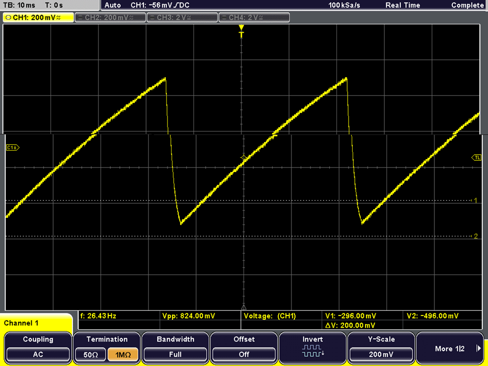
Test Point A
When taking an oscilloscope trace from test point A, located at pin 3, we observed a repeating square wave with a frequency of around 26 Hz.
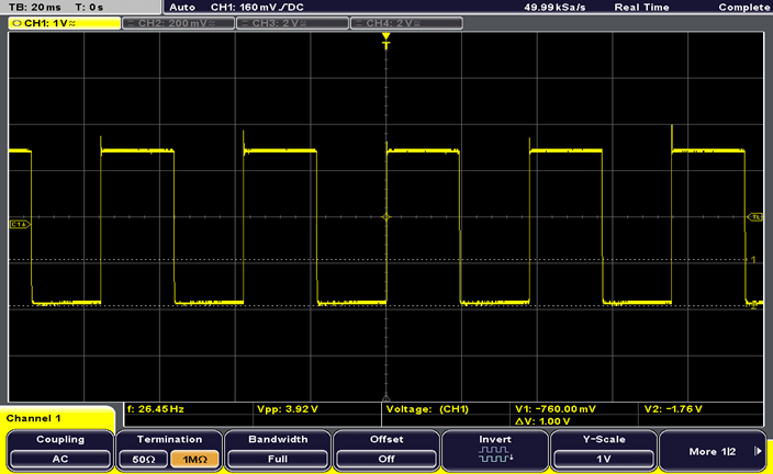
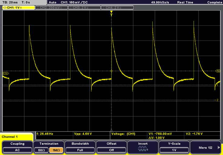
Test Point B
We then took an oscilloscope reading at test point B, located at pin 5. This produced the differentiated square wave that we read from test point A. This is the capacitor suddenly charging and then discharging with some overshoot.
Test Point C (1)
Upon taking a reading at test point C, it is apparent that there is small bursts of waves. These bursts are what controls the current in the infra-red LED’s using a PNP transistor.
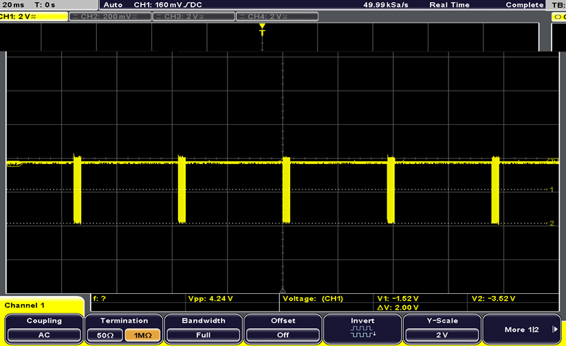
Test Point C (2)
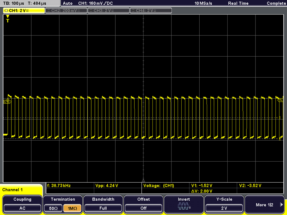
When zooming in to the bursts, it is made clear that they are composed of square waves oscillating at roughly 40 KHz.
Test Point D (1)
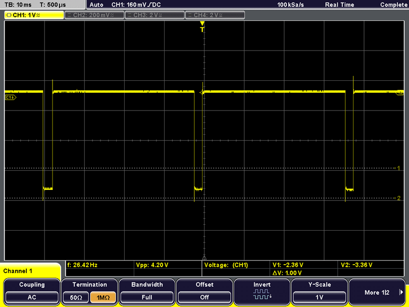
Test point D is where we can see the output of the IR sensor. The trace goes from 0 to 1 with 1 indicating an obstacle. LED’s are used on the circuit to act as a physical identifier of an obstacle being detected.
Test Point D (2)
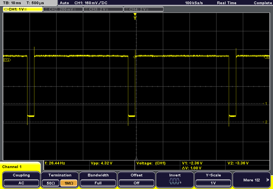
With this test point being exactly the same as the one described previously, except this is now the output of the opposite IR sensor.
Test Point E
Test point E is located at the junction where the 3.3V supply is connected to pin 9 through a 1MΩ resistor. This shows the threshold voltage being used for detection operating at roughly 25Hz.
