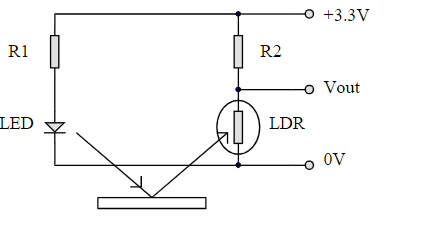
Circuit Diagram
Moving onto white-line following now and we used the circuit design provided in the micro mouse handbook as designed by Dr Timothy Davies.


White-Line sensor construction
It was then time for the construction of the white line sensor circuit, undertaken by Mohammed and Jack. The circuit consists of a white LED, a 330 Ohm Resistor, a 10 Kilo-Ohm resistor and alight dependent resistor. The voltage seen across this LDR will be used to determine where the white line is in relation to the mouse.
Integrating the code
Once the circuit was built, it was then up to Thomas to implement the code in a way to allow for the white-line following. It was decided that the thresholds for the white would be under 1750, while anything above would be classed as black. Due to the sensors being close, there was quite a bit of instability in our first attempt as seen in the video.

The trees that are slow to grow bear the best fruit.
– Molière