01. The infrared circuit

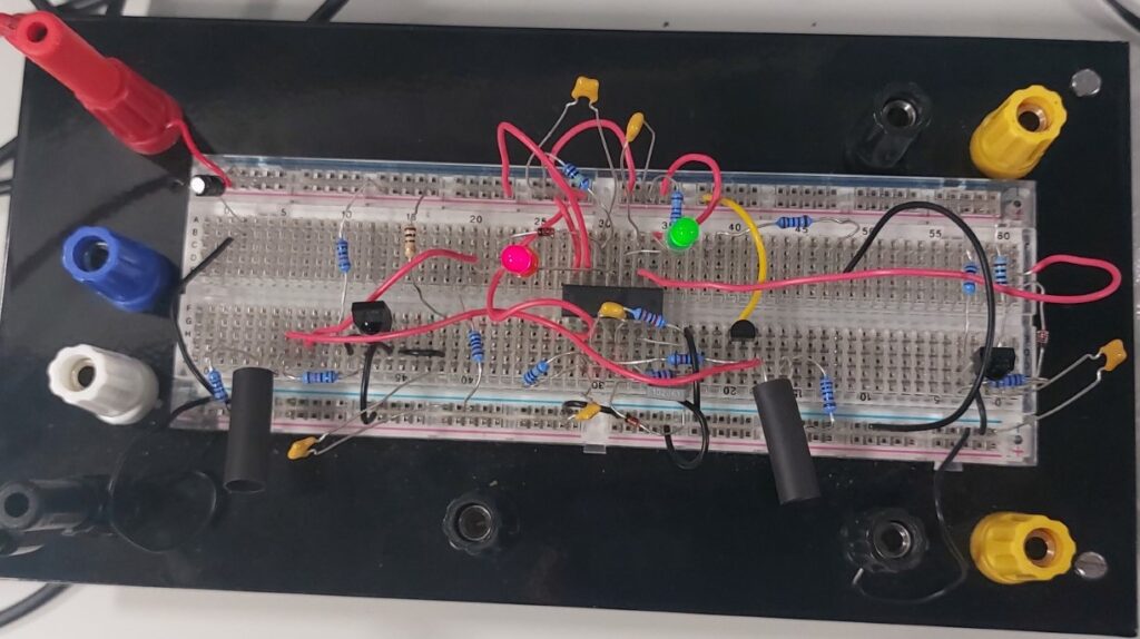
The infrared circuit was designed and constructed to enable the micromouse to avoid contact with walls and obstacles. An infrared LED paired with a receiving sensor was used to build the circuit. The combination of optical filtering, modulation, and demodulation results in a sensor sensitive to light reflected from obstacles, but not environmental light sources. The IR sensors are complex yet suitable as they operate outside the visible spectrum, making them less prone to interference than alternatives like LDRs. Infrared Receiver was chosen to operate the circuit at 40kHz. The circuit generates 40kHz bursts pulsed at 20Hz for the IR emitters, protecting the sensors from interference while conserving current since the emitters aren’t constantly on. We then constructed the circuit onto a breadboard to understand the component compatibility so that they could be implemented directly onto the PCB.
02. Oscilloscope traces
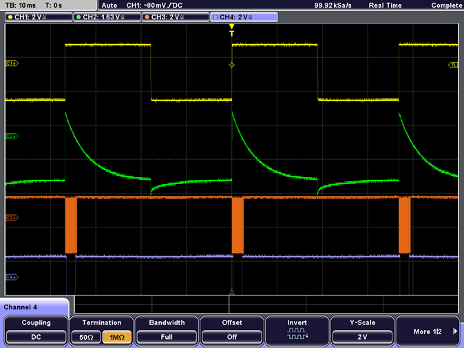
After completing the breadboard prototype, an oscilloscope was connected at various points to analyze circuit performance. The traces show the circuit modulates the IR LEDs at two frequencies – 40 kHz pulses at 20Hz. This dual modulation further immunizes the sensors against interference while reducing current draw since the LEDs are only briefly illuminated. With these results, we implemented two sensors on a small PCB using a single integrated circuit. As mentioned, the circuit generates the required signal for the IR emitters. A Rohde & Schwarz 2024 Digital Oscilloscope can validate the signals at each stage. Pin 3 shows a 20Hz square wave, followed by the differentiated square wave at Pin 5. The final trace at Pin 4 and across all emitters displays the 40kHz bursts pulsed at 20Hz. By testing these output signals, we identified and resolved issues on the PCB. Once the signals aligned with expectations, we confirmed the IR emitters were fully functional. In summary, the oscilloscope enabled analysis of the modulation scheme and verification of appropriate signaling to the IR emitters across the circuit blocks. This testing methodology allowed debugging and validation of the emitter functionality.

