

An important feature of our Micromouse was the ability to extract data during runtime, and this was the reason we decided to implement an OLED screen.
One of our ‘special features’ was the built-in ability to calibrate the maximum and minimum light levels measured by the light-dependent resistors, upon which our white line avoidance and combat modes relied. We experimented with the ability to store these values in the microcontroller’s non-volatile memory (EEPROM), however for our purposes it proved to be quite unstable. We instead decided to implement the calibration test in a way that didn’t overwrite or save any values, but instead just communicate them to us so we could hardcode the new values in the program.
The immediate obvious solution was to use the Serial Monitor, but this relied upon a constant USB tether between the device and the computer, and so again, was unsuitable. We finally decided that the best solution would be to fit a small OLED screen to the microcontroller as it would not only be a solution to this problem but would also serve as a useful debugging tool in many future applications. This turned out to be good planning, as by the end of this project the OLED screen was a crucial aspect of the device that significantly reduced the debugging and testing process.
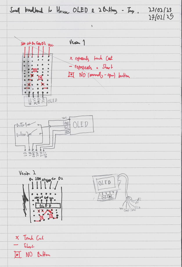
It was important to us that our Micromouse featured a sturdy and purposeful design, and we tried to avoid unstable mounting/positioning of our components wherever possible. Instead of flimsily blue tacking the OLED screen to the PCB and using loosely connected breadboard jumper wires, we designed a small breadboard that would allow the OLED to stand upright using its 4 connection points, with the added benefit of 2 small buttons which would be used to control the content on the screen. All of the output pins from the breadboard that would be connected to the microcontroller could then be in one big cable using heat shrink tubing, to reduce the number of loose wires cluttering the Micromouse. A rough design can be seen below:
Unfortunately, shortly after our prototype of the design was completed, we were informed that we should not solder the OLED screens permanently, as they were to be removed and re-used. At this point I recalled from previous research that the microcontroller featured multiple separate I2C (the communication method used by our OLED) interfaces, and so a second “Wire” object could be declared in the program (as the first was being used by the Seesaw Port Expander. This would allow the OLED screen to be directly and securely connected to the breakout board as seen in the image below. Luckily, there was an array of four connection ports on the section labelled “AUX” on the breakout board that happened to be the exact right sequence: voltage supply, ground, and two data ports with I2C capability. The four touch bar switches were also instead used as the buttons to interact with the screen.

We wanted our OLED screen to display some useful information during the operation of our white line, combat, and obstacle avoid programs, but the calculations and decisions made during these programs proved to be very time-sensitive and the OLED screen consumed quite a bit of time to continuously write to, and we couldn’t think of any useful ideas that were worth the sacrifice of responsiveness.
Other applications of our OLED include:
- A small bitmap startup splash-screen (a mouse shaped like the lowercase delta character 🙂)
- A startup “log” that prints to the screen all of the components and objects that are created and tested successfully. If a component is causing issues and preventing the proper operation of the device – often this could be the seesaw not initializing properly, or a sensor with a blank reading – then it would be obvious which component was causing the problem as the last log statement printed would be “starting [component]” before operation halted.
- A program selector after startup that would wait for one of four modes – white line, obstacle avoid, combat, debug – to be selected using the touch bars
- An in-depth “debug” mode that featured three sub-modes – max speed calibration, LDR calibration, and an advanced PID gain calibration.
