
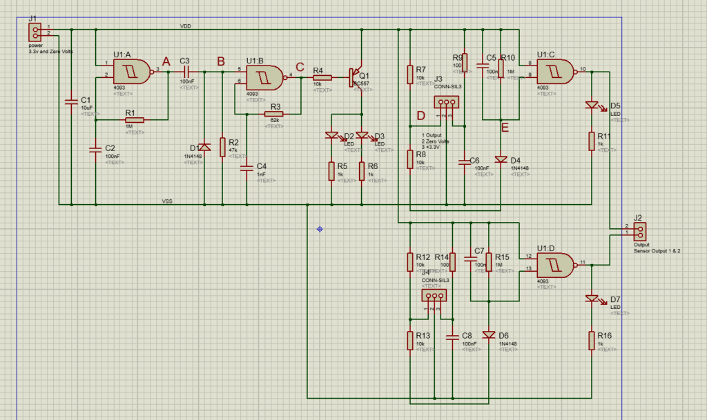
Below, you will be able to see our software-built PCB design, as obtained from the original schematic diagram.


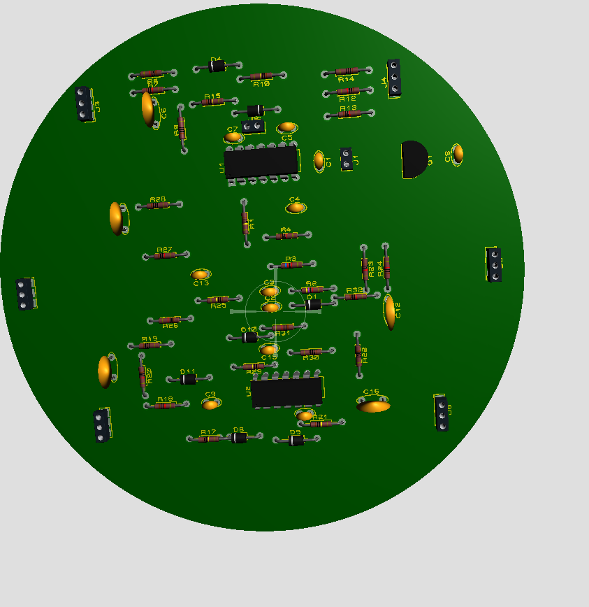
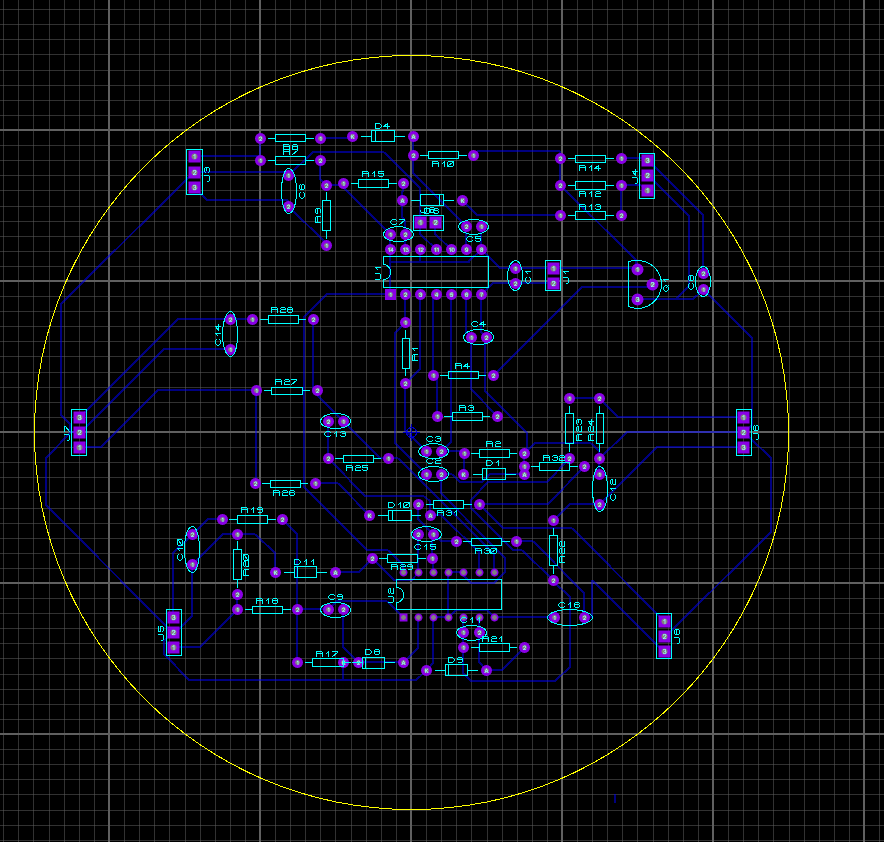
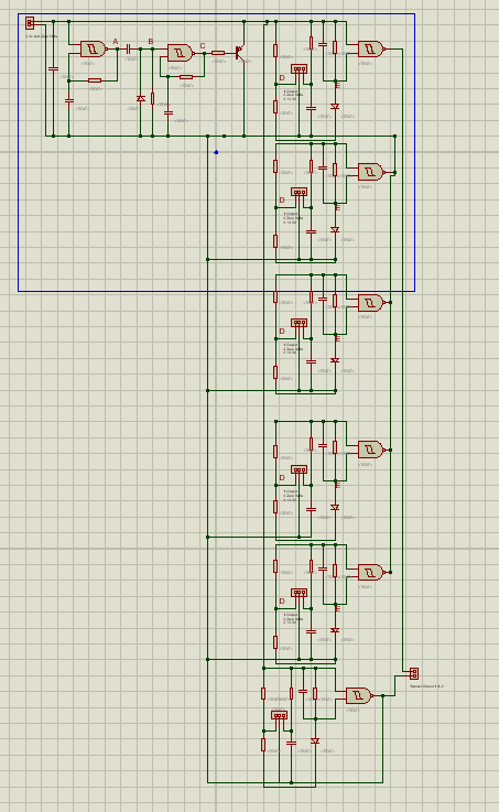
Furthermore, the diagrams below represent the new schematic capture, PCB layout and 3D visualiser of the updated PCB design.
The highlight of the new feature lays in the minimal or lack of IR LEDs, rather, we have a shield of sensors.
Components used:
- x2 CD4093 quadruple 2-input Schmitt NAND gate
- x14 100nF capacitors
- x1 10uF electrolytic capacitor
- x1 1nF capacitor
- x1 1kOhm resistor
- x6 100Ohm resistor
- x13 10kOhm resistor
- x6 1MOhm resistor
- x1 47kOhm resistor
- x7 1N4148 diode
- x6 IR Sensors
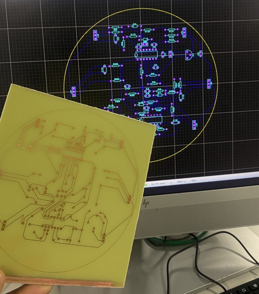
Picture of physical PCB design containing special features.
The special features in our case was a WiFi module to remotely control the movement of the micro-mouse and also the absence of IR LEDS, instead our robot consisted of a shield of IR sensors and therefore added ultrasonic sensors.