Obstacle Avoidance
The micromouse is made up of sensors for productivity and effectiveness of the motors, it has the microswitch, the white line sensors, the ultrasonic sensors and finally the infrared sensors. First, the Infrared sensors and microswitches are the main sensors for detecting obstacles. Luckily for us, the microswitch was attached to our prototype for building the motors.
Now for the infrared sensors, we had to build according to the schematic given to us, as the Infra-red sensors are far more useful in detecting avoidance even before collision. We have a complex circuit to generate and demodulate the light at two frequencies, at 40KHz pulsed at 20Hz. The double modulation makes the sensors, immune to interference and reduces the current consumption.
Our goal for Obstacle avoidance, is for the micromouse must avoid contact with walls and every obstacle without physical contact, we would like the micromouse to move away swiftly from obstacle.
To test our circuit, we connected the probes at every points A to E to confirm that our circuit was connected properly and can be used on our PCB
Below we have the schematic design of the Infrared sensor with an optical filter to detect obstacles.

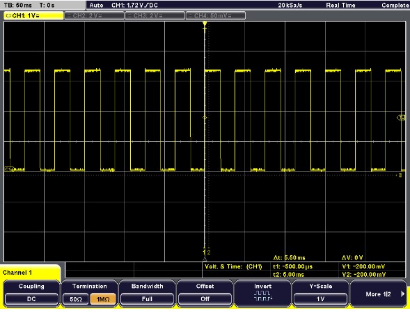
Point A
For point A, on the schematic above, there should be a 20Hz square waveform on the oscilloscope. That is shown below, and it proves that we connected Point A correctly.

Our result on the oscilloscope is shown on the right.
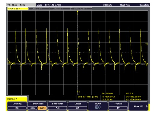
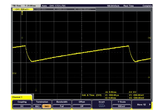
Point B
Moving onto to Point B, according to the handbook, we should be getting a differentiated square wave, which is shown below.

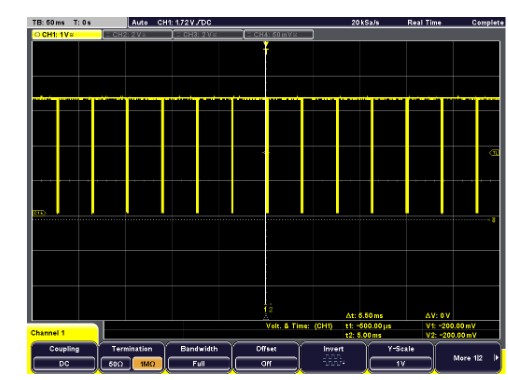
Point C
Point C has a burst of 40KHz square wave.

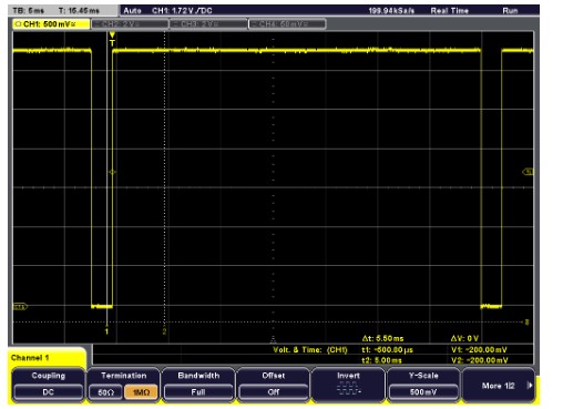
Point D
Point D is the output of the IR Sensors

Point E
Point E is the threshold voltage for detection

P.S The schematic design is given for the Infrared circuit is given by Dr Jobling and Dr Davies our tutors.
Obstacle Avoidance Read More »

