PCB design arrangement
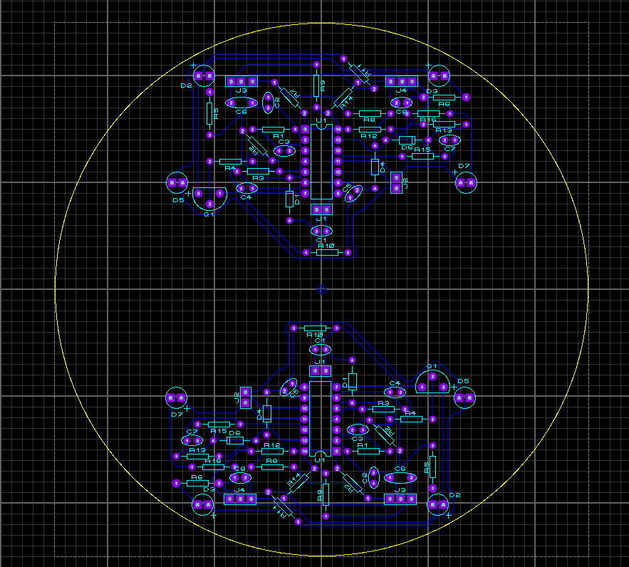
The software utilised to arrange the PCB was called Proteus. Using Proteus allowed us at Team Golf to re-organise the components into an efficient manner at the front and at the back so that they were as efficiently placed as possible. Furthemore, in the scenario that this PCB was to be manufactured on an industrial scale, the efficient placement of components would mean that it would take less time to manufacture. Manager James was responsible for the PCB design and half of the soldering, which Bright assisted with.
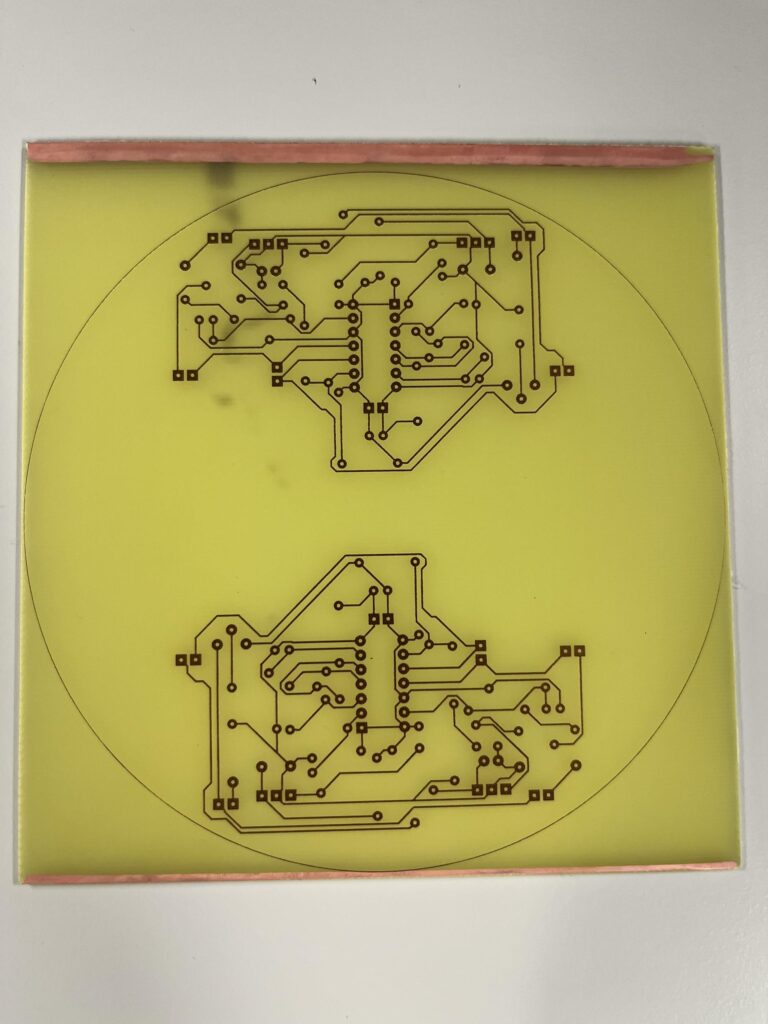
PCB design after copper track application
This is the PCB design after the copper tracks have been applied as per the PCB design schematic via Proteus. The next step was to cut out the unnecessary plastic and punch the holes with a pneumatic hole puncher.
PCB design partially soldered
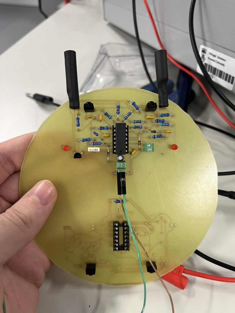
This is the PCB after the excess plastic was removed and the holes punched for the soldering of components. As it can be seen on the left-hand side, 50% of the soldering was complete, with two 2-way terminals for input voltage and output voltage. A quick test of this circuit showed that it operated as expected, meaning that the red LEDs on the left and right side of the PCB activated when an object was placed in front of the infra-red emitter.
PCB mounted with wheel accomodation
This is the PCB after the excess plastic was removed from the inside of the circle on the left and right hand side, allowing for the accomodation for the DC motor wheels of the micromouse. This allowed for a low-profile design that proved to be more lightweight and compact than the standard design.
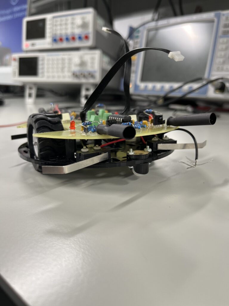
PCB mounted with Raspberry Pi Pico
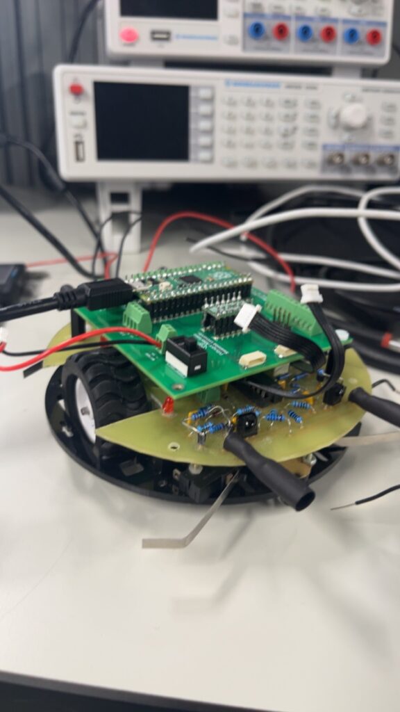
This is the PCB after the Raspberry Pi Pico was mounted on top of the infra-red PCB. Doing this showed us how much space the micromouse would take up when it was fully assembled. All in all, the PCB design proved to be well placed to accomodate for the DC motor wheels which drastically reduced the height of our micromouse.
