After we finished the design of our PCB, we moved on to printing it out and preparing it for soldering. We began with drilling holes into the PCB for the components to sit in, then cut the corners off the board and sanded it down into the shape of a circle.
With the PCB ready, we still had the infrared sensors sensors to take care of. Setting up a simple range finding circuit, we tried to find 2 sensors of equivalent ranges to use for the design. This part is very important because the code would be the same for both sensors.
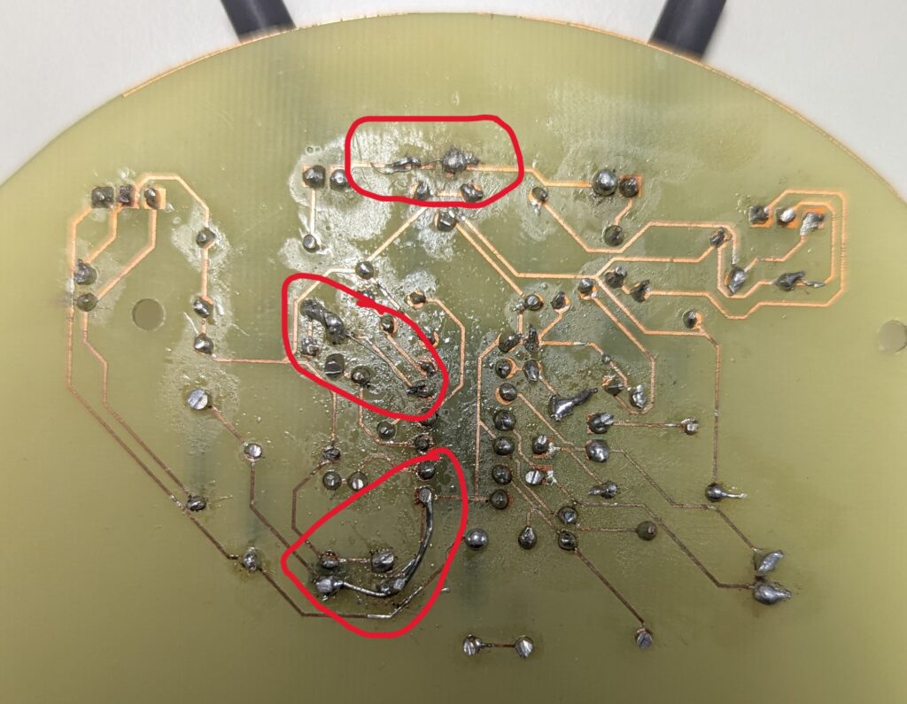
After picking out the right sensors, we were prepared for soldering. We began to slowly solder in all the components onto the board one by one starting with the, however due to mistakenly not rubbing out enough of the film on the plastic board, we had a hard time getting the solder to stick to the board, which caused many problems along the way. One of the issues we came across was broken tracks, which we had to learn to fix as this problem as it occurred multiple times.
After we finished the bulk of the soldering and connected it the main body and raspberry pi, we noticed that one of the LEDs did not light up suggesting that one of the IR sensors did not work. However for the inspection, that did not matter as the Micromouse still accomplished the obstacle avoidance test and with time running out that semester, we had to leave those problems for next semester.
0 Comments