
This is an Infra-Red Sensors that we have improved through multiple designs. The circuit modulates the light at two frequencies, at 40 kHz pulsed at 20Hz. This double modulation makes the sensor even more immune to interference, and also has the effect of reducing the current consumption as the LED is only illuminated for a small part of the time. Two sensors can be incorporated on a small PCB using just one integrated circuit. Due to the length issue of the circuit board, we have added an additional board to make the circuit appear less crowded. In addition, we have also redesigned the circuit so that the LEDs are all on the same board for easy observation.
- Waveform at point A:
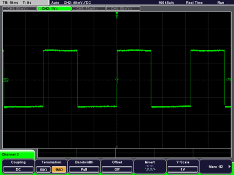
The waveform at point A gives us a 20 Hz square wave, which is at Pin 3.
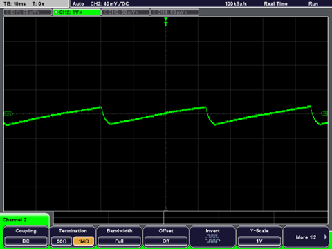
- waveform at point B:
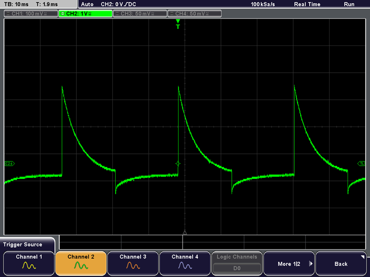
The waveform at point B gives us a differentiated square wave, which is at Pin 5.
- waveform at point C:
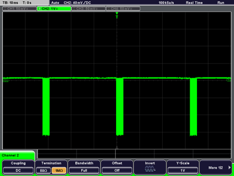
The waveform at point C gives us a bursts of 40 kHz
square wave, which is at Pin 4.
- waveform at point D:

The waveform at point D gives us the output of
IR sensor, which is at the sensor.
- waveform at point E:
The waveform at point E gives us the threshold voltage for detection, which is at Pin 9.