White line circuit schematic
Following this schematic using the LDR as a potential divider to output an analogue value to determine if the sensor is over a white or black surface.

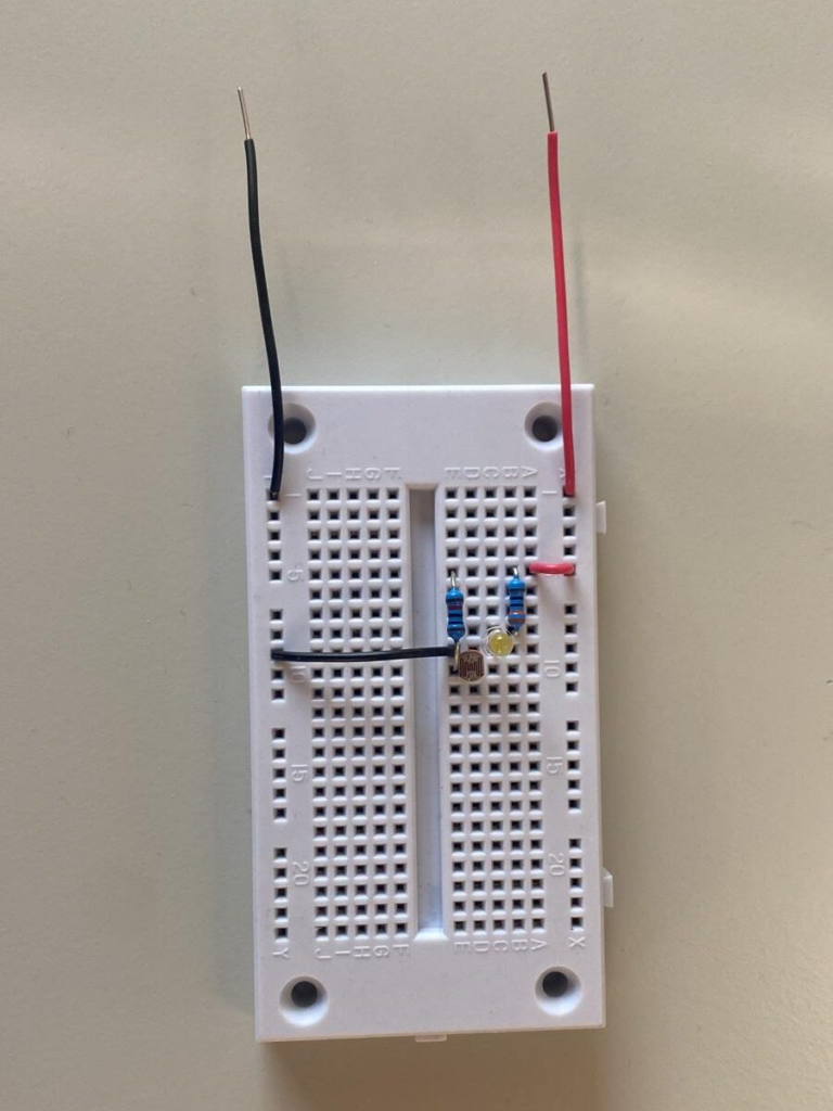
Test circuit on breadboard
Firstly building the circuit firstly on a breadboard to test and make sure it works properly with the desired configuration.

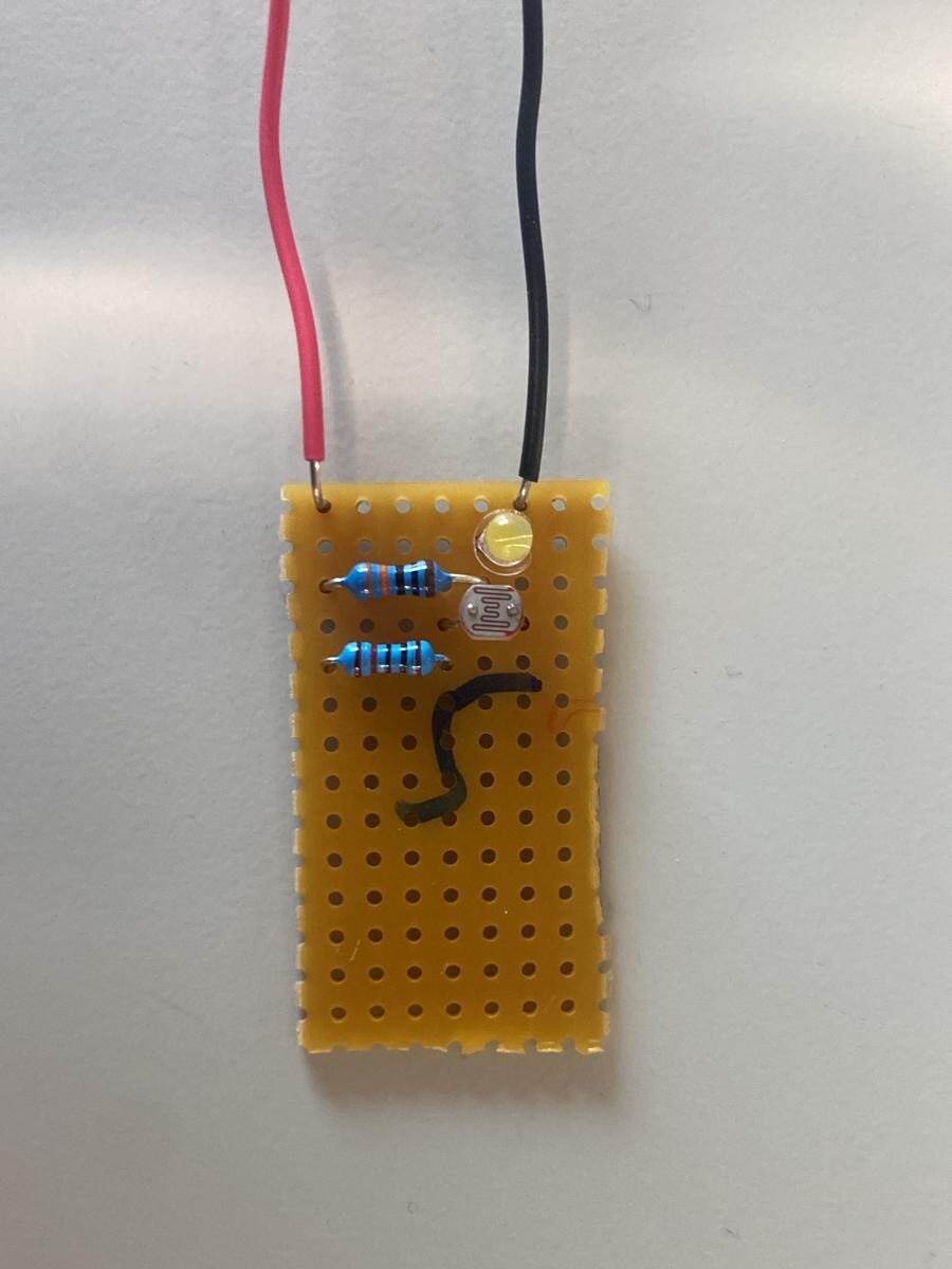
First white line built on vero board
Building it onto a vero board and installing it to the base of the micro-mouse to begin coding the white line following mode.

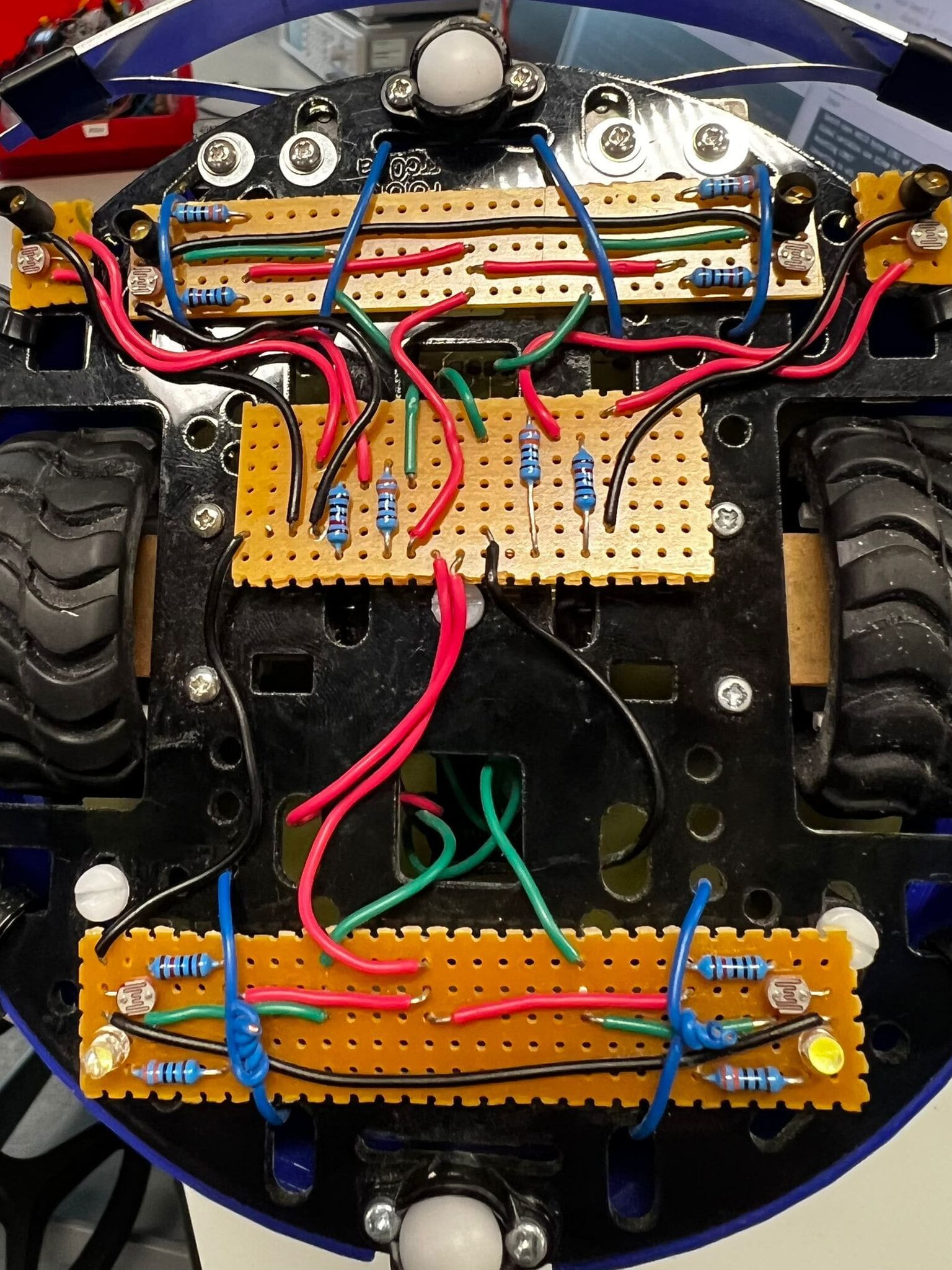
Completed white line sensors on micro-mouse
We ended up rebuilding all the circuits, choosing to have 6 white line sensors, 4 front sensors for white line following and the 2 rear sensors for combat. The primary function of the outside front sensors was to detect corners when in white line following mode, this meant that the central sensors could free wheel instead of breaking which makes the mouse drive more seamlessly. The reason for having 2 sensors at the back was so if the mouse is being pushed off the arena in any direction it would be able to pick it up and react quicker.
