The obstacle avoiding will be done using infrared sensors and emitters, however before this we will use touch bars to test the speed of the motors.

This is our micromouse using just the touch bars. We noticed that the motors speed was slightly off balanced, but with assistance were able to fix this using the software to balance the speed.
Once the motors were functional. The infrared sensors and infrared emitters will then be used. These sensors were used to limit interference from the environment.
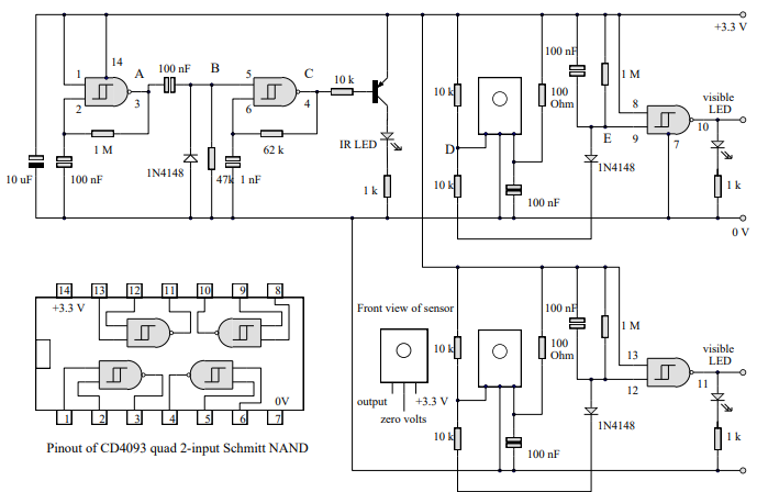
This is a complex circuit we were provided with. You will notice it has letters from A to E. These are the testing points that will be used later on.
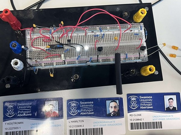
This is the breadboard circuit we created for the infrared sensors following the diagram above. You can see the LEDs are illuminated, this shows it is working, however further testing is needed.
Once the breadboard circuit was finished, we began working on the PCB design, this was our final design:
We decided to opt for two emitters and sensors on the front, but on the left, right, and rear we only opted for sensors. The idea behind this was to limit the amount of infrared we’re emitting to make it harder for other micromouse to detect us but being able to detect theirs.
