This is the testing stage of the infrared sensor circuit.
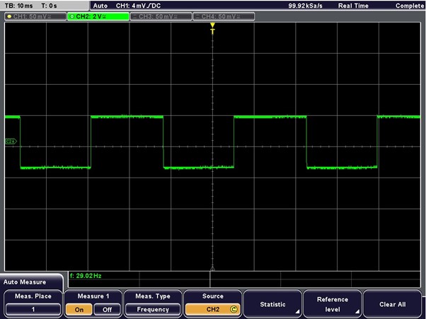
Test Point A
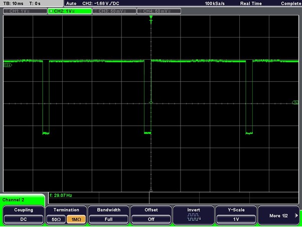
Starting with test point A, the first gate, this is a 20kHz oscillator. As expected, we did get a square wave, however ours oscillates at 29kHz. But upon inspection it was functioning as intended, so we continued with the testing, to see if our outputs were affected by this.
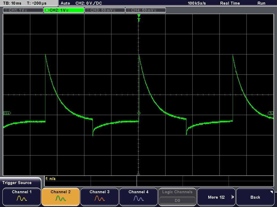
Testing Point B
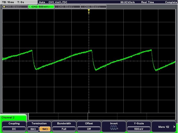
Testing point B is just the square wave from A but differentiated. This is what it should look like.
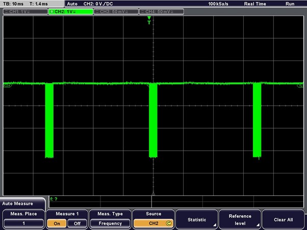
Testing Point C
This testing point is a gate that shoots short bursts, that oscillate at 40kHz. It is shooting out bursts of frequency, but we need to measure the frequency.
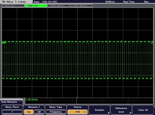
Testing for Frequency.
This is what is inside the short bursts of testing point C. It is clearly showing 40kHz, which is what we were hoping for.
Testing Point D
This is the output for the infrared sensor and corresponds to the envelope of the burst waveform.
Testing Point E
This is the threshold voltage for detection
Now that the infrared sensor is working, the PCB construction can begin.