The white line following will use light dependant resistors (LDRs), where the resistance will change depending on the surface. The circuit will also consist of a white LED, this is because the light emitted will reflect off of the surface underneath the micromouse, the darker the surface the less light will reflect off onto the LDR, increasing its resistance, and vice versa for a white surface. The first thing when building the white line following was to construct the circuit onto a breadboard:
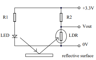
The resistor values used are R1 = 330Ohms and R2 = 10kOhms.
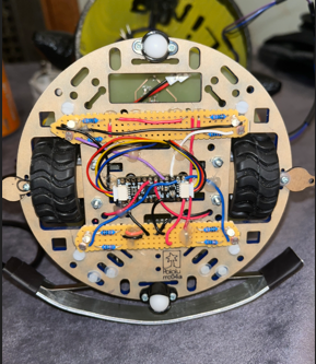
Once the breadboard version was working, it was constructed onto a vera board:
This is the finished LDR circuit on the micromouse. We have opted to use four LDRs each connected to an analogue port on the seesaw breakout board. Now that the hardware aspect is finished, the next step is to take analogue readings of each sensor under both conditions, white and black surface.